img

Manufactures and Traders of
Rf Anechoic Chambers & Rf Absorbers

img

Manufactures and Traders of Positioner System
& waveguides components

img

Manufactures and Traders of microwave Test Benches
& Horn Antenna’s

img

about us

WAVETECH is established in Faridabad (Haryana) India in middle of year 2006 with an aim of manufacturer high quality RF, Microwave instruments and components and provide quality service to our esteem Clientele.

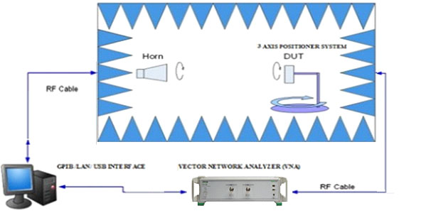
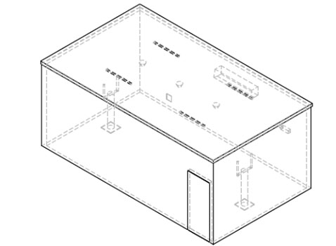
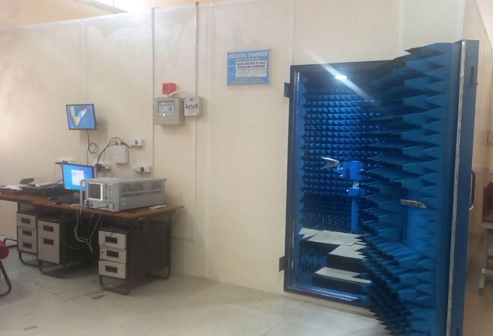
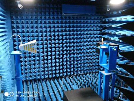
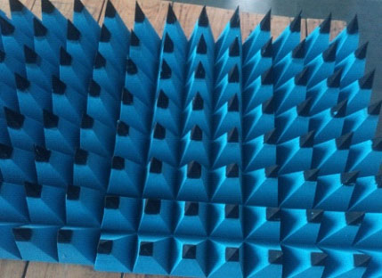
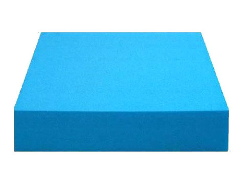
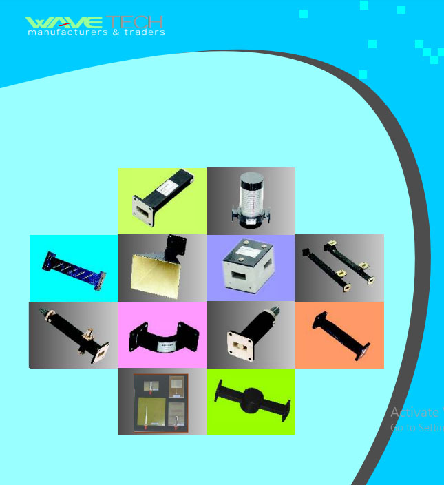
WAVETECH specialized in passive microwave components for industrial and academic purpose, RF Anechoic Chambers, RF Cables, RF Connectors, RF Absorbers, microwave educational training kits, waveguides, Broad band and horn antennas, Coaxial components, MIC kits and antenna assembly.

Our reputed customers are IIT Institutes, IIIT, NIT, Engineering Collages, Industrial and government organizations.

Our primary goals are to produce quality products and service to customers and create a niche in market and at the same time maintain pleasant work environment for our employees.

WAVETECH are committing our full resource, technical expertise and talents to achieve these simple yet most important goals. Our team started manufacturing of microwave components in X- Band. Now we are proud to say that, we have manufacturer RF Anechoic chambers, products from Frequency Range 500MHz to 140GHz.

We look forward to your interest to work together with WAVETECH to feel the difference.

from WAVETECH

VED PARKASH (Proprietor)

our products

img

ANECHOIC CHAMBER WITH POSITIONER SYSTEM

WAVETECH provide Anechoic Chambers for Measurement of RF properties of antennas. The chamber has been designed keeping in mind the requirement of UHF RF ID system components. We also use this chamber to carry out antenna measurements, Mono static/ Bi-static RCS measurements, near field measurements, Bore sight measurements, Radome testing etc. Anechoic chamber range rom small compartments the size of household microwave ovens to once as large as aircraft hangars. The size of chamber depends on the size o object and frequency ranges being tested.

img

LAYOUT OF ANECHOIC CHAMBER

COMPLETE SET UP COMPONENTS

  • Comprise of RF Anechoic Chamber
  • VNA instrument
  • 1 Axis Transmitter positioner system
  • 3 Axis Receiver Positioner System
  • Measurement Software – Lab view based
  • Reference Broadband Horn Antenna’s
  • Antenna under Test
  • PC for Interfacing
img

RF ANECHOIC CHAMBER(outer VIEW)

STRUCTURE MATERIALS AND DETAILS

  • PAN Panel self supported structure will be provided.
  • Made out of MS Pipes, GI Sheets and bolted structure.
  • GI Sheet will be of standard brands - Tata Steel, JSW Steel, Essar Steel or similar.
  • MS Pipe will be of standard brands – Apollo, A-one, Tata or similar.
  • Welded structure and then bolted sheets and over that absorbers lining will be there.
  • Outer aesthetics will be provided with Laminated sheets.
img

RF ANECHOIC CHAMBER(inner VIEW)

rf absorbers and details

  • PU foam based RF Absorbers.
  • Size (Height) varies from 3 inches (75 mm) to 36 inches (900 mm).
  • Standard Base Size of 610 mm x 610 mm.
  • Absorbers models are WFU4, WFU6, WFU9, WFU12,WFU18, WFU24,…..& so on.
  • Walkway absorbers will be provided to access and move inside the chamber.
  • Absorbers on all sides will get pasted with adhesive. Floor absorbers along with walkway will be placed and can be moved if required.

common features of rf absorbers

  • Temperature resistant
  • 0.5 Watt/in2 or 775 Watt/m2 Power Handling
  • Long performance warranty
  • Tested as per IEEE standards
  • Fire retardant as per NRL 8093
  • Long product life up to 20 years
img

pyramid absorbers

reflectivity table of ram

Model No. Thickness 600 MHz 1 GHz 2 GHz 4 GHz 8 GHz 12 GHz 18 GHz 24 GHz 40 GHz
FC5 50 mm -10 -12 -14 -15 -16 -20 -24 -28
FU4 100 mm -18 -22 -25 -30 -32 -34 -38 -40
FU6 150 mm -20 -25 -30 -32 -34 -38 -40 -42
FU9 225 mm -16 -22 -28 -32 -34 -38 -40 -43 -47
FU12 300 mm -20 -25 -30 -34 -38 -40 -44 -47 -50
FU18 450 mm -25 -30 -35 -38 -41 -45 -48 -50 -50
FU24 610 mm -30 -35 -38 -41 -45 -48 -50 -52 -52
img

flat absorbers

  • Flexible, light weight used in interference suppression applications.
  • Available in standard base size of 2' x2' (60cmx60cm) and height from1 cm to 5cm.
img

walkway absorbers

  • Low- density rigid polystyrene foam is used to encapsulate a standard pyramidal or wedge absorber.
  • Walk on Absorber provide access to chamber to move and mount / replace the DUT.
img

rf doors

  • Single knife edge door with both sides level.
  • Door size will be 3 ft x 7 ft (WH).
  • Be-Cu fingers at periphery and Gaskets at joints.
  • Entry door to provide access to the chamber.
  • Standard Hardwares for the door.
img

consumable accessories

img

fire alarm system

  • Fire Alarm system comprise of complete set including – Two Zone Digital control panel, two numbers of smoke detector, Hooter and Manual call-point.
  • Detectors mounted inside and all control and power from outside the chamber. Panel and concerns mounted outside on wall of chamber.
img
img
img
img

led lights

  • LED Surface lights – 24 V panel
  • Standard Make – Orient, Havells, Polycab.
  • White color light.
  • Hanged with help of Rod / Brackets inside the chamber.
  • Quantity will be calculated based on size of chamber & site requirement.
img

split air conditioner

  • 1, 1.5, 2 tonne split AC will be provided (depends on site requirement ).
  • Inner unit will be mounted inside the chamber.
  • Water pipe and other pipe will be taken out through pipe penetration.
  • Supply will taken from outside the chamber through EMI Filter.
  • Standard Make – Carrier, Godrej, Samsung or equivalent.
img img img

emi filter

SINGLE PHASE FACILITY EMI FILTER MF420-2CF

Technical Specifications
datasheet

Specification Details
Rated Voltage 250VAC
Operating Frequency 50/60Hz
Rated Current 32A
No. of Lines 2 Lines
Shielding Effectiveness 100dB from 500kHz to 40GHz
Overload Current Rating 6x Rated Current for 8 Sec
Discharge Resistance 1.5MΩ (Internally Connected)
Test Voltage 1500Vdc each line to case
1414Vdc line to line
Leakage Current at 240Vac <5mA
Maximum Temperature Rise on Full Load 35°C
Operating Temperature -25°C to 85°C
Input Connection 6 Sqmm Cable Connection through Knockout Hole
Output Connection 6 Sqmm Cable Connection through threaded pipe
Enclosure Material CRCA with Nickel Plating
Overall Mechanical Dimension 220mm X 120mm X 90mm

All dimensions are in mm

  • EMI Filter will be 32 A, single phase, 2 wires.
  • Lights, AC, electric points concern to chamber will be connected through EMI Filter.
img img img

cctv setup

key features

  • 2MP high performance CMOS
  • 1920×1080 resolution
  • Full time color
  • 3.6mm,6mm fixed lens
  • Upto 40m white light distance
  • OSD menu,3DDNR,trueWDR
  • 4in1 video output(switchableTVI/AHD/CVI/CVBS)
  • IP67
  • Up the coax(HIKVISION-C)
Category Specification
Image Sensor 2 MP CMOS image sensor
Resolution 1920 (H) × 1080 (V)
Frame Rate PAL: 1080p@25fps, NTSC: 1080p@30fps
Min. Illumination Color: 0.0005 Lux @ (F1.0, AGC ON), 0 Lux with white light
Shutter Time PAL: 1/25s to 1/50,000s, NTSC: 1/30s to 1/50,000s
Slow Shutter Max. 16x
Lens 3.6mm, 6mm fixed lens
Field of View 3.6mm: Horizontal FOV: 83.0°, Vertical FOV: 44.4°, Diagonal FOV: 98.0°
6mm: Horizontal FOV: 51.0°, Vertical FOV: 28.5°, Diagonal FOV: 58.7°
Lens Mount M16
Day & Night Color
Angle Adjustment Pan: 0° to 360°; Tilt: 0° to 180°; Rotate: 0° to 360°
Synchronization Internal synchronization
WDR (Wide Dynamic Range) 130dB
Image Mode STD / HIGH SAT
AGC Yes
White Balance Auto / Manual
HLC Yes
BLC (Backlight Compensation) Yes
Privacy Mask 4 programmable privacy masks
Motion Detection 4 programmable areas
Functions Brightness, Sharpness, 3D DNR, Mirror, Smart light
Video Output 1 HD analog output
Switch Button TVI / AHD / CVI / CVBS
Operating Conditions -40°C to 60°C (-40°F to 140°F), Humidity: 90% or less (non-condensation)
Power Supply 12V DC ±25%
* You are recommended to use one power adapter to supply power for one camera.
Power Consumption Max. 4.2W
Protection Level IP67
Material Front Cover: Metal
Main Body: Plastic
Bracket: Metal
White Light Up to 40m
Communication Up the coax, Protocol: HIKVISION-C (TVI output)
Dimensions 223.1 mm × 77.1 mm × 82.6 mm (8.78" × 3.04" × 3.25")
  • CCTV Set includes DVR, 2 Cameras, HDD, Power supply, LED Screen.
  • Standard make – HikVision, CP Plus or equivalent.
  • Total control and mounting outside on the wall of chamber and Cameras will be mounted inside chamber with help of Rods/Brackets.
  • LED Screen of Size – 32 inches will be provided (as per client requirement). Standard make – AOC, Frontech, Fingers or Equivalent.
img img

earthing

  • Maintenance free Earthling.
  • 3 mtr long copper rod will be burried in 10 ft long hole of size 100 mm.
  • A well-designed Earthing system is essential for any electrical installation to avoid dangers associated with fault currents.
  • Strip / 6 mm wire will be routed to connect Pit / line with chamber with help of Lugs.
  • If earthling strip / point available near to the chamber room then we connect it further with the chamber.

RADIATION PATTERN MEASUREMENT SYSTEM - POSITIONER SYSTEM

img

1+3 axis position system including

3 axis reciever antenna positioner

  • The System has the ability to adjust the antenna position in Azimuthal, Polarization & elevation directions.
  • Synchronized with VNA for automatic measurements.
  • Feature /software E & H Pattern combined to give 2D ,3D pattern.
  • Angular Motion can be done in different step sizes and it is user selectable.
  • Wide range of step sizes like from 0.09 deg to 0.18,0.9,2.7,5.4,18......any angle in multiple of 0.18 deg.
  • Elevation & Polarization Movement will be + 90 degree.
  • Able to move and minimize the distance between Tx & Rx.
img

1 Axis Transmitter Antenna Positioner

  • The System has the ability to adjust the antenna position in Polarization directions.
  • Mechanical / Laser alignment.
  • Polarization movement from 0 to 360 degree.
  • Height is adjustable can be adjusted same as Receiver.
  • Maximum load Capacity : 15 kg
img

4 axis reciever positioner

Azimuth, elevation, Polarization same as 3-Axis positioner system including X-Axis extra movement 1 meter positive 50 centimeter and negative 50 centimeter, least count 1mm.

measurement parameters

  • 2D E/H Radiation Pattern
  • 3D Radiation Pattern
  • Gain Measurement.
  • RCS Measurement.
  • Axial Ratio.
  • Measuring the S-Parameters(S11,S12,S21 and S22)
img

lab view based single screen access

  • Both plots & readings will be provided in single software window. Also you can see live changes in plot during measurement.
  • Software is provided with Six select frequency & measurement option. For each frequency point you have to run the measurement again.
  • Complete parameter measurements including 2D, 3 D pattern, Gain, Axial Ratio Graph plotting & Measurements.
  • Interfaced with VNA & PC for automatic measurements.
  • Single screen access to measurement & control, real time view too.

report & data save options

  • The data will be saved in excel format in the particular Folder in PC .
  • The Plots can also be accessed within the software w.r.t measurement parameter.
  • User can retrieved the past data on the software for analysis.
img

control panel (drives, smps, controller)

img

control and communication

  • Both Positioner control Panel and VNA controlled through LAN and provided with detailed operational manual.
  • On command positioner will move and take reading at each step and in same way it complete the full rotation.
  • Software customization is provided. User can add measurement terms by providing the particular details.
img

2d pattern

img

3d pattern

img

six freq patterns in single run

img

manual rotation of axis

img

hybrid stepping motors

Step Angle Degree 1.8°
Step Angle Accuracy ±5% (full step, no load)
Temperature Rise 80°C Max
Ambient Temperature -10°C to +50°C
Insulation Resistance 100MΩ min. 500VDC
Dielectric Strength 500VAC for one minute
Shaft Radial Play 0.06 mm Max. (450g-load)
Shaft Axial Play 0.08 mm Max. (450g-load)
  • Hybrid stepper motors with different configurations will be provided.
  • Stepper drives and PVC gear boxed will be used to reduce the step size to 0.09 degree.
  • Motor will be of 2 coils, 4 wires and accordingly it get connected.
  • Single screen access to measurement & control, real time view too.
img img

reference horn antenna (0.5 to 1.5GHz)

  • Frequency Range: 500 MHz – 1.5 GHz
  • Antenna Type: Horn
  • VSWR: 2.0 to 3.0 (Typ.)
  • Connection Type: N (Female)
  • Mounting brackets will be provided for Mounting.
  • Gain file will be provided along with test reports & Readings.
img img

broadband dual rig reference antenna 1 to 18 GHz

  • Frequency Range : 1 GHz – 18 GHz.
  • Input Power: up to 100 Watts CW/200 Watts for pulsated applications.
  • VSWR: < 2.0 to 3.5 (Typ.)
  • Gain: 4 dBi to 20 dBi (typ.)
  • Connection type: SMA (Female).
  • Mounting plates will be provided for Mounting.
  • Antenna test report will be provided – with RL, VSWR, Radiation plots & Gain.
img img

broadband dual rig reference antenna 18 to 40 GHz

  • Frequency Range :18 to 40 GHz.
  • Input Power: up to 100 Watts CW/200 Watts for pulsated applications.
  • VSWR: < 2.0 (throughout the band).
  • Gain: 10 dBi to 20 dBi (typ.)
  • Connection type: 2.92 mm (Female).
  • Mounting plates will be provided for Mounting.
img

ultra low loss rf cables dc to 40 GHz

  • Frequency Range : 500 MHz to 40 GHz.
  • Pre-connectorized Ultra Low Loss RF Coaxial Cable assembly for Ka band application.
  • Impedance: 50 ohm
  • Frequency: DC~40 GHz
  • VSWR: ≤ 1.35:1
  • Insertion Loss: ≤ 3.6 dB/m @40 GHz
img

our clients

img
img
img
img
img
img
img
img
img
img
img
img
img

contact us

Address

Wavetech
Plot No: - 217/3, Mailwara, Near Sector - 18, Old Faridabad 121002, Haryana, India.

call us

0129-4177616 , 9911796330, 9312526184

mail Us

salewavetech@gmail.com, wavetechsystems06@gmail.com, wavetech_products@gmail.com